Introduction
Milling is one of the most capable machining processes available — but the operation type you choose shapes everything from surface finish to tool life. Each method serves a distinct purpose and produces fundamentally different results.
Choosing the wrong operation for a job leads to poor surface quality, wasted material, accelerated tool wear, and higher costs.
This guide breaks down the most important milling operation types, how they differ mechanically, and how to match the right one to your part geometry, material, and production requirements.
Key Takeaways
- Milling removes material using a rotating multi-point cutter to produce flat surfaces, slots, profiles, and complex contours
- Main operation types include face milling, plain (slab) milling, end milling, angular milling, and form milling—each defined by cutter orientation and surface type
- Face milling excels at large flat surfaces
- End milling dominates slots, pockets, and 3D profiles requiring tight tolerances
- Operation selection depends on part geometry, material machinability, tolerances, and production volume—choosing wrong adds rework costs
What Is Milling and Why Do Operations Matter?
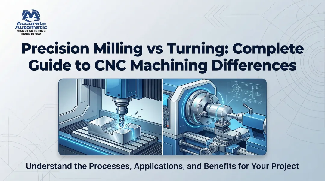
Milling is a cutting process where a rotating multi-point cutter removes material from a workpiece as it is fed against the cutter. Unlike turning (where the workpiece rotates) or drilling (where the tool moves axially), milling is the go-to process for producing flat surfaces, slots, profiles, and complex contours across metals, plastics, and composites.
Milling covers a family of related processes, each defined by how the cutter is oriented relative to the workpiece, the direction of feed, and the type of surface being produced. Using the wrong operation leads to poor finish, inaccurate dimensions, or tool failure. Choosing correctly improves both efficiency and part quality.
Machine type shapes which operations are practical, which is why understanding the two main configurations matters:
- Vertical Machining Centers (VMCs) — spindle perpendicular to the table; versatile for general engineering and 3D profiling
- Horizontal Machining Centers (HMCs) — spindle parallel to the table; gravity aids chip evacuation, making them better suited for heavy material removal and complex castings
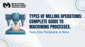
Types of Milling Operations
Milling operations are not one-size-fits-all. Each type is defined by specific cutter geometry, orientation, and workpiece setup—making some ideal for flat surfaces, others for contours, slots, or multi-feature production in a single pass.
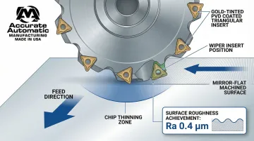
Face Milling
In face milling, the cutter axis is perpendicular to the workpiece surface. Cutting occurs primarily at the end corners (face) and periphery of the cutter, producing flat, smooth surfaces. Face mills with multiple indexable inserts are standard, and the feed runs horizontally across a wide surface area.
Where plain milling cuts along the cutter's circumference, face milling acts through the cutter's end face. That distinction makes it the preferred choice for squaring off large flat surfaces and hitting fine surface finish targets—not for deep material removal.
Key strengths:
- Machines large flat surfaces quickly with high-quality finishes in one pass
- Standard in automotive (engine blocks), aerospace (structural panels), and general fabrication where flatness is critical
- Wiper inserts eliminate secondary grinding, achieving surface roughness as low as 0.4 µm (16 µin) at higher feed rates
- High-feed face mills with 10°–20° entering angles unlock extreme material removal rates through chip thinning
Limitations: Not suited for deep slots, pockets, or profiling. Requires machine rigidity to prevent chatter, and cutter runout can leave trochoidal surface marks (arc-pattern scallops) if not managed.
Plain (Slab) Milling
Plain milling (also called slab or surface milling) is a peripheral operation where the cutter axis runs parallel to the workpiece surface. Cutting happens along the circumference of wide, arbor-mounted cutters as the workpiece feeds beneath them on a milling table.
The key distinction from face milling: plain milling uses the cutter's periphery rather than its face, making it well suited for wide, flat stock removal across the full width in fewer passes—typically on horizontal machines.
Key strengths:
- Heavy roughing cuts on wide, flat surfaces (removing large volumes from raw bar or plate stock)
- Helical-tooth cutters (45°–60° helix angles) reduce vibration and produce smoother finishes
- Used in machine tool manufacturing and structural component prep
Limitations: Less versatile than end milling for complex profiles. Requires a horizontal milling setup, and is less common in modern CNC shops where end milling and face milling dominate.
End Milling
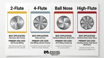
End milling uses a cutter with cutting edges on both its end face and peripheral sides—allowing it to plunge into material, cut along its side, and machine in multiple directions. End mills come in configurations including 2-flute, 4-flute, ball nose, and flat end, making them the most versatile cutter type in CNC machining.
Unlike face mills or slab mills built primarily for surface work, end mills produce slots, pockets, profiles, contours, and 3D shapes in a single setup. 2-flute variants can drill their own starting holes without pre-drilling; 4-flute variants are better suited for side milling with higher core strength.
Key strengths:
- Handles slot milling, pocket milling, 2D/3D profiling, shoulder milling, and finish work
- The go-to operation for CNC machining centers in aerospace, medical device, mold-making, and precision parts manufacturing
- Flute count must match material type: 2-3 flutes for aluminum (maximum chip evacuation), 4 flutes for general steel, 5-7+ flutes for hardened materials
Limitations: Smaller-diameter end mills deflect and break under heavy loads, limiting depth of cut. Deep pockets require multiple passes and careful feed-rate management. Tool wear accelerates in hardened materials without proper speeds, feeds, and coolant.
Angular Milling
Angular milling produces flat surfaces at a specific angle to the cutter axis—neither parallel nor perpendicular. The cutter is positioned to cut chamfers, V-grooves, dovetails, serrations, and other angled features using single- or double-angle cutters with common included angles of 45°, 60°, and 90°.
Key strengths:
- Produces chamfered edges, dovetail slides, serrated surfaces, and angular grooves on precision components
- Especially valuable in toolmaking, fixture fabrication, and mechanical assembly where precise angular features are required
- Works on both horizontal and vertical mills by tilting the workpiece in a universal vise
Limitations: Angular cutters run slower than plain or side cutters. Each angle requires a specific cutter, increasing tooling costs. Compound angles demand skilled setup or an adjustable head to hit dimensional targets.
Form Milling
Form milling uses specially shaped cutters to machine irregular or complex contours in a single pass—concave and convex profiles, corner radii, half-round recesses, and custom shapes. The cutter geometry directly mirrors the final profile it produces.
Key strengths:
- Efficiently reproduces complex profiles such as gear tooth forms (involute gear cutters), half-round recesses, quarter-round radii, and custom grooves
- Standard in tooling, die making, and gear manufacturing
- Delivers consistent, repeatable output across high production volumes without repositioning
Limitations: Formed cutters are expensive, application-specific, and can't be repurposed for a different profile. Setup time is higher. For low quantities, fly cutting (single-point form milling) may be more economical. Advanced CAM strategies using dynamic/trochoidal milling can reduce machining time by up to 70% with standard end mills—removing the case for custom form tools in low-volume runs.
Gang and Straddle Milling
Gang milling mounts two or more cutters on the same arbor to machine multiple surfaces simultaneously. Straddle milling takes a narrower approach—two side milling cutters spaced on an arbor machine both sides of a workpiece at once, controlling width precisely. Both methods prioritize throughput in production environments.
Best suited for:
- Milling hexagonal or square profiles in a single pass
- Cutting parallel slots and multiple grooves simultaneously
- High-volume duplicate part runs requiring consistent multi-surface results
Limitations: Setup complexity is higher than single-cutter operations, and both methods depend on horizontal milling machines. In modern shops, CNC multi-axis machining has largely taken over the role gang milling once dominated.
How to Choose the Right Milling Operation
The correct choice of milling operation is determined by part geometry, required tolerances, material type, available machine setup, and production volume—not simply by what's most familiar or available.
Feature Geometry and Surface Requirements
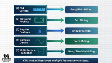
The part drawing drives the choice:
- Flat surfaces → face or plain milling
- Slots and pockets → end milling
- Angular features → angular milling
- Complex curves → form milling
When multiple features are needed, end milling's versatility often makes it the single best option on a CNC machining center.
Material and Cutter Selection
Harder materials require slower speeds, more rigid setups, and carbide tooling. Softer materials (aluminum, brass) allow higher feed rates and more aggressive cuts. This affects which operation is practical within available machine power and cutter specifications.
Cutter pitch matching is critical:
- Coarse pitch (fewer teeth, larger chip gullets): First choice for unstable operations, long-chipping materials like aluminum, and roughing—generates the lowest cutting forces
- Fine/close pitch (higher tooth density): Used for finishing operations and high-productivity roughing in stable conditions like cast iron—ensures more than one tooth is always engaged
Material and cutter decisions also tie directly into volume planning—what's optimal for a single prototype often isn't the right call for a 500-piece run.
Production Volume and Setup Complexity
- One-offs and short runs: end milling or face milling minimizes setup changes without sacrificing versatility
- High-volume duplicate parts: gang milling or straddle milling cuts cycle time per part significantly
- Complex geometries across medium volumes: CNC multi-axis end milling is typically the most cost-effective path
Contract shops like Accurate Automatic MFG—offering CNC milling, CNC turning, and screw machine work under one roof—can evaluate all three factors together and recommend the most direct route from drawing to finished part.
Common Mistakes to Avoid When Selecting a Milling Operation
Operation selection errors are among the most avoidable sources of cost and quality problems in a machine shop. Three mistakes come up repeatedly.
Over-Specifying the Operation for the Job
Reaching for face milling with expensive indexable tooling on a simple slot — or using form milling for a profile an end mill handles in two passes — inflates tooling and setup costs without improving the result. Match the operation to the job, not to the most capable tool available.
Ignoring Machine Capability and Rigidity Requirements
Each milling operation makes specific demands on the machine. Running heavy plain milling on an underpowered vertical mill, or pushing angular milling cutters at excessive speeds, reliably produces:
- Chatter and vibration
- Poor surface finish
- Premature tool failure
Verify spindle power, arbor rigidity, and machine configuration before committing to an operation.
Selecting Based on Familiarity Instead of Fit
Defaulting to end milling for every job — including wide-surface work that face milling handles faster and more economically — means leaving efficiency on the table. The right operation is the one that fits the geometry, the machine, and the production volume, not simply the one the operator knows best.
Conclusion
Milling operations—from face and end milling to angular, form, and gang milling—each exist to address specific part geometry requirements. Understanding the distinctions between them is what separates efficient, high-quality machining from costly trial-and-error.
Choosing the right operation comes down to reading the part correctly, understanding your machine's capabilities, and matching tooling to material and volume demands. Accurate Automatic MFG applies that decision-making process to every job—selecting the right milling approach based on part requirements, tolerances, and production volume before cutting begins.
Frequently Asked Questions
What is the most common type of milling operation?
Face milling and end milling are the most widely used operations. Face milling dominates large flat-surface work in automotive and aerospace applications, while end milling is the go-to for CNC slot, pocket, and profile machining across industries.
What is the difference between face milling and peripheral milling?
In face milling, cutting occurs primarily at the end face of the cutter to produce flat surfaces with the spindle perpendicular to the workpiece. In peripheral (slab) milling, cutting happens along the cutter's circumference—typically used for large, flat stock surfaces on horizontal machines.
What materials can be machined using milling operations?
Milling can be applied to metals (steel, aluminum, brass, titanium), plastics, composites, and wood. Cutter selection, speed, and feed are adjusted based on material hardness and machinability—with carbide tooling and coatings required for harder alloys.
What is the difference between climb milling and conventional milling?
In conventional (up) milling, the workpiece is fed against the cutter's rotation—better for rough surfaces and older machines with backlash. Climb (down) milling feeds with the cutter's rotation and is generally preferred for CNC machines, producing a better finish and extending tool life up to 50%.
Which milling operation is best for creating slots and keyways?
End milling is the most common approach for slots and round-end keyways, with cutter diameter matching the required slot or key width precisely. Woodruff keyslot cutters handle semicircular keyways.
How does CNC milling improve precision compared to conventional milling?
CNC milling uses computer-controlled axes to execute programmed toolpaths with consistent speed, feed, and depth—eliminating operator variability. Standard tolerances are held to ±0.005" (0.13 mm), with precision work achievable to ±0.001" (0.025 mm) or better. That level of repeatability across high-volume production runs is not practical with manual setups.