Introduction
Turning is a subtractive machining process that produces cylindrical components by rotating a workpiece against a stationary cutting tool. Despite advances in multi-axis machining and additive manufacturing, it remains the most efficient method for hitting tight tolerances and smooth surface finishes on round parts across aerospace, automotive, and medical applications.
Many manufacturers struggle with selecting the right machining process for rotationally symmetric parts, often over-complicating designs that could be efficiently produced through turning operations. With the global CNC turning market projected to reach $40.61 billion by 2030, driven by a 6.6% annual growth rate, procurement teams and design engineers who understand turning's capabilities can reduce per-part costs and avoid over-engineering components.
TLDR:
- Turning removes material from rotating workpieces using stationary cutting tools to create cylindrical shapes
- CNC turning achieves tolerances of ±0.005" standard, ±0.001" or better for precision work
- Common operations include straight turning, facing, boring, threading, and grooving
- Works across metals (steel, aluminum, titanium, brass) and engineering plastics
- Best suited for rotationally symmetric parts — non-round features require milling
What Is Turning in Machining?
Turning is a subtractive machining process where a workpiece rotates on its axis while a stationary single-point cutting tool removes material from its outer surface. The result is a cylindrical shape with precise dimensional control. The cutting tool moves linearly—either parallel to the rotational axis for longitudinal turning or perpendicular to it for facing—removing material as chips.
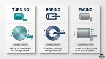
Turning vs. Boring vs. Facing
While all three fall under lathe operations, each serves a distinct purpose:
| Operation | Surface | What It Does |
|---|---|---|
| Turning | External | Reduces diameter and creates cylindrical features on the outside of a rotating workpiece |
| Boring | Internal | Enlarges or finishes a pre-existing hole using a boring bar |
| Facing | End face | Moves perpendicular to the rotational axis to create a flat, smooth end surface |
From Manual Lathes to CNC Precision
The conceptual foundations of numerical control emerged in the 1940s through John T. Parsons' vision of controlling machine tools via coded instructions. In 1952, MIT and Parsons collaborated to create the first NC machine—a modified Cincinnati Milacron Hydrotel. By the 1960s, Computer Numerical Control (CNC) technology enabled real-time feedback and sophisticated programming. By 1989, CNC machining became the standard for large-volume manufacturing.
Modern CNC turning brought automated precision through computer-controlled tool paths and constant surface speed control, improving repeatability and reducing human error that came with manual operation.
What Is a Turned Part?
A turned part is any component produced through this process. That precision opens the door to a wide range of industrial components, including:
- Shafts — cylindrical rods found in transmissions, engines, and rotating assemblies
- Bushings — sleeves that reduce friction between moving parts in mechanical assemblies
- Pins — small fasteners used for alignment or connection
- Threaded fasteners such as bolts, studs, and screws with external threads cut during turning
How the Turning Process Works
Core Mechanics
The workpiece is secured in a chuck, collet, or between centers on a lathe. It rotates at a programmed speed measured in revolutions per minute (RPM). The cutting tool moves linearly along or across the workpiece to shear material in chip form. How well these elements work together depends on three process parameters—and the cutting forces they generate.
Key Process Parameters
Two fundamental parameters control material removal, surface finish, and tool life:
Cutting Speed:
- Measured in surface feet per minute (SFM) or meters per minute (m/min)
- Represents the relative velocity between the cutter and workpiece surface
- Calculate spindle speed using:
RPM = (12 × SFM) / (π × Diameter)for Imperial units
Feed Rate:
- Measured in inches per revolution (IPR) or millimeters per revolution (mm/rev)
- Defines how far the tool advances with each workpiece rotation
- Higher feed rates increase productivity but may compromise surface finish
Depth of Cut Trade-offs
Depth of cut—combined with feed rate and speed—directly affects productivity, cutting forces, and tool wear:
- Roughing operations: Aggressive cuts (deeper depth, higher feed) remove material quickly but generate higher cutting forces and tool wear
- Finishing operations: Light cuts (shallow depth, lower feed) produce precision surface finishes and tight dimensional tolerances
Those cutting forces don't act uniformly — each component affects machine rigidity, workpiece stability, and chatter risk in a distinct way.
The Three Principal Cutting Forces
| Force Component | Direction & Impact |
|---|---|
| Tangential (Cutting) Force | Acts tangentially to rotation; largest force component; primary driver of power consumption and tool deflection |
| Axial (Feed) Force | Acts parallel to the workpiece axis in the feed direction; causes less deflection than radial forces |
| Radial (Thrust) Force | Acts perpendicular to the workpiece axis; deflects the tool away from the workpiece, causing vibration and chatter |
To minimize radial deflection and vibration, engineers should use entering angles close to 90° (0° lead angle), which maximizes the portion of feed force directed axially rather than radially.
Managing these forces also depends on what your cutting tool is made of — and the gap between HSS and carbide is significant.
Cutting Tool Materials: HSS vs. Carbide
Cemented carbide inserts have largely replaced HSS in CNC turning environments, and the property comparison explains why:
| Property | High-Speed Steel (HSS) | Cemented Carbide |
|---|---|---|
| Hardness | 62–66 HRC | 75–85 HRC equivalent |
| Heat Resistance | Softens above 540°C–600°C | Maintains stability at 800°C–1000°C+ |
| Cutting Speed | Low to moderate | 3 to 5 times higher than HSS |
| Tool Life | Shorter; wears quickly on hard materials | 2 to 10 times longer than HSS |
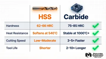
HSS still has a place in manual operations, heavily interrupted cuts, or softer materials where carbide's brittleness is a liability — but for production CNC turning, carbide inserts are the practical default.
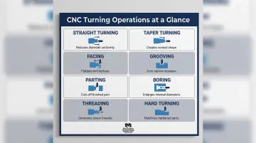
Types of Turning Operations
Turning encompasses several distinct operations, each suited to producing specific geometric features or surface characteristics. Understanding each operation helps clarify how a precision machine shop sequences work to deliver complete, finished components.
Straight Turning
The cutting tool moves parallel to the rotational axis of the workpiece, reducing the outer diameter along the part's length to create a uniform cylindrical surface. This is the most common turning operation, used to produce shafts, pins, and cylindrical sections of complex parts.
Taper Turning
The cutting tool moves at an angle relative to the rotational axis, gradually reducing or increasing diameter to produce a conical shape. Taper turning is commonly used in machine spindles, tool holders, and components requiring precise angular surfaces for mating or alignment.
Facing
The cutting tool moves perpendicular to the rotational axis, removing material from the end of the workpiece to create a flat, smooth face. Facing is often the first and last operation in a turning sequence—first to establish a reference surface, and last to achieve final length and surface finish.
Grooving and Parting
Grooving cuts channels to a set depth on external, internal, or face surfaces. Grooves serve as oil reservoirs, O-ring seats, or snap ring locations.
Parting — also called cutoff — cuts all the way through the workpiece to separate a finished component from the bar stock. Both operations are essential in high-volume CNC turning for efficient production.
Boring
Boring is the internal equivalent of turning — enlarging or finishing an existing hole using a boring bar. The boring bar's rigidity matters more here than in most operations, since bar diameter and overhang directly affect vibration and accuracy. Internal boring operations are particularly sensitive to radial cutting forces that can cause deflection and chatter.
Threading, Knurling, and Hard Turning
Threading uses a form tool synchronized to the workpiece rotation to cut external or internal threads. The tool follows a helical path at a precise feed rate matching the desired thread pitch.
Knurling presses a textured pattern onto the workpiece surface for improved grip or aesthetic purposes — commonly seen on tool handles and adjustment knobs.
Hard turning machines hardened materials above 45 HRC as an alternative to grinding, using specialized PCBN (Polycrystalline Cubic Boron Nitride) or ceramic inserts. According to Sandvik Coromant's technical guide, hard turning can reduce machining time and costs by up to 70% compared to traditional cylindrical grinding.
Here's a quick reference for how these operations compare:
| Operation | Tool Path | Primary Purpose |
|---|---|---|
| Straight Turning | Parallel to axis | Reduce outer diameter uniformly |
| Taper Turning | Angled to axis | Create conical surfaces |
| Facing | Perpendicular to axis | Flatten workpiece ends |
| Grooving | Radial, set depth | Channels for seals, rings, lubrication |
| Parting | Radial, full depth | Separate finished part from stock |
| Boring | Parallel to axis (internal) | Enlarge or finish existing holes |
| Threading | Helical path | Cut external or internal threads |
| Hard Turning | Parallel to axis | Machine hardened materials (45+ HRC) |
Shops like Accurate Automatic MFG routinely combine several of these operations in a single setup — reducing handling time and holding tighter tolerances than multi-machine workflows allow.
Advantages of Turning in Machining
Dimensional Accuracy and Tight Tolerances
Turning consistently produces high-precision cylindrical features, making it the go-to process for components requiring tight dimensional control. Standard CNC turning tolerances run ±0.005" (0.13mm), with precision lathes reaching ±0.001" (0.025mm). That level of accuracy is essential for critical coaxial features in aerospace actuators, medical implants, and automotive transmission components.
Contract manufacturers like Accurate Automatic MFG pair turning with CNC milling and screw machine operations in-house, which means tightly toleranced turned parts can move through subsequent operations without leaving the facility.
Material Versatility
Turning works across a wide range of materials:
- Metals: Steel alloys, aluminum, titanium, brass, stainless steel
- Engineering plastics: Nylon, PEEK, Delrin, polycarbonate
- Wood: For specialized applications
Machinists adjust cutting parameters—speed, feed, depth of cut, and tooling selection—for each material to optimize tool life and surface finish.
Production Efficiency
CNC turning is fast, repeatable, and can run with minimal operator intervention once programmed. The Asia-Pacific region accounts for 55.5% of the global CNC turning market, driven heavily by automotive production volumes where turning operations produce brake components, pistons, and transmission parts at scale.
Modern CNC lathes support lights-out manufacturing through features like:
- Automated tool changers for uninterrupted multi-operation runs
- Bar feeders that load raw stock without operator intervention
- Part catchers that collect finished components automatically
Short Lead Times
Turning enables short lead times compared to other precision processes, especially for prototype and mid-volume production runs. Fast setup and programming on modern CNC lathes mean parts can move from CAD model to finished component in days rather than weeks. That turnaround speed matters most during product development, where design changes can happen quickly and waiting weeks per iteration isn't realistic.
Limitations of Turning
Geometry Constraint
Turning is best suited to rotationally symmetric parts — cylindrical and conical profiles. Non-round or prismatic shapes typically require milling or multi-axis machining, making turning one step in a broader workflow.
Parts requiring both cylindrical and prismatic features benefit from mill-turn centers that combine a rotating workpiece with live milling tools, consolidating operations and cutting setup time.
Tooling and Equipment Costs
CNC lathes and associated tooling — carbide inserts, boring bars, toolholders — represent significant capital investment. A modern CNC turning center runs $50,000 to $500,000 depending on size, axis count, and automation level. At production volume, reduced cycle times and consistent quality bring those costs back down.
Tool Wear and Scrap Management
The repetitive cutting motion causes predictable insert wear, requiring regular indexing or replacement to maintain part quality. Operators track two primary wear indicators:
- Flank wear: Index at 0.38–0.50mm for roughing, 0.25–0.38mm for finishing
- Crater wear: Monitor the rake face for material buildup or deformation
Turning also generates chips — called swarf — that must be collected and recycled. Chip control matters: long, stringy chips can wrap around the workpiece or tooling, causing damage or safety hazards.
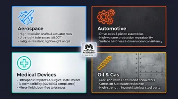
Common Industries and Applications of Turning
Primary Industries Relying on Turned Parts
| Industry | Typical Turned Components | Key Requirements |
|---|---|---|
| Aerospace | Shafts, actuator rods, hydraulic fittings, landing gear components | High-precision complex geometries, extreme stress tolerance, tight tolerances |
| Automotive | Axles, pistons, brake components, transmission parts | Thermal stability, high-volume repeatability, cost efficiency |
| Medical Devices | Implants, instrument housings, surgical tool components | Ultra-precision, biocompatibility, regulatory compliance |
| Oil and Gas | Valves, connectors, drill components | Corrosion resistance, high-pressure tolerance, reliability |
What Makes a Part a Good Candidate for Turning?
Design characteristics that favor turning include:
- Cylindrical or axially symmetric profiles defined primarily by diameter and length
- Coaxial features—multiple diameters, grooves, and threads sharing a common centerline
- Round features requiring tight dimensional tolerances and precise concentricity
- Bearing surfaces or sealing interfaces where fine surface finish is critical
Accurate Automatic MFG serves clients across all of these industries, combining CNC turning with milling, screw machine operations, and engineering support to deliver finished components that meet each sector's specific requirements.
Frequently Asked Questions
What is the difference between turning and milling?
In turning, the workpiece rotates at high speeds while a stationary single-point cutting tool removes material to create cylindrical shapes. In milling, the workpiece is held stationary while a multi-bladed rotating cutting tool removes material to create flat surfaces and complex profiles.
What is the difference between turning and boring?
Turning removes material from the external (outer) surface of a rotating workpiece to reduce diameter. Boring removes material from the internal surface, enlarging or finishing a pre-existing hole using a boring bar inserted into the workpiece.
What materials can be turned in machining?
Turning handles metals (steel, aluminum, titanium, brass, stainless steel), engineering plastics (nylon, PEEK, Delrin), and wood. Cutting parameters—speed, feed, depth of cut, and insert selection—are adjusted for each material to optimize results.
What is CNC turning and how does it differ from manual turning?
CNC turning uses a computer-controlled lathe that follows a pre-programmed tool path automatically, delivering higher repeatability and precision than manual lathes. Manual turning requires an operator to move the cutting tool by hand, relying on skill and experience to achieve desired dimensions.
What tolerances can turning achieve?
CNC turning can typically achieve standard tolerances of ±0.005" (0.13mm), with precision lathes reaching ±0.001" (0.025mm) or better depending on machine rigidity, tooling quality, and setup. These tight tolerances make turning suitable for precision components with exacting requirements in aerospace, medical, and automotive applications.
What is hard turning and when is it used?
Hard turning machines workpieces with hardness above 45 HRC (typically 55–65 HRC) using PCBN or ceramic inserts. It's often used as an alternative to grinding on hardened parts after heat treatment, cutting machining time and costs by up to 70%. Surface finishes of Ra 0.17–0.35 µm are routinely achievable.