Introduction
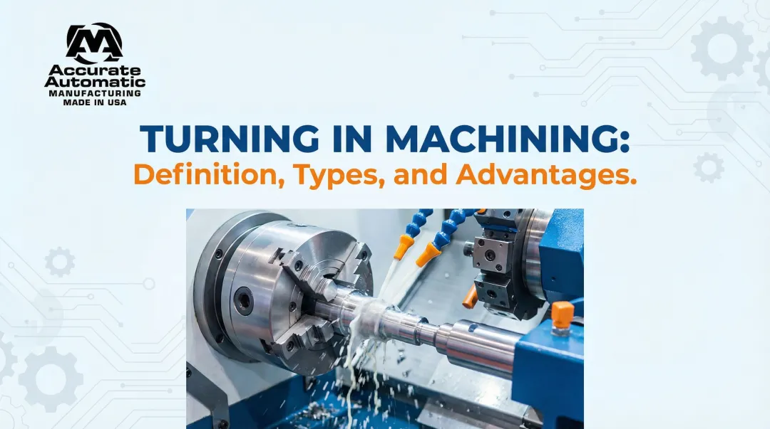
A single micron of deviation can mean a rejected aerospace component or a recalled medical implant. That's the reality precision metal turning operates in — a subtractive machining process where a rotating workpiece is shaped by a stationary cutting tool to achieve tight dimensional tolerances and smooth surface finishes.
For design engineers, procurement teams, and machine shop buyers, understanding what separates precision turning from standard turning is critical. In aerospace, defense, and medical manufacturing, parts either meet spec or they don't.
Metal turning is one of the oldest machining operations, yet its precision variant is frequently misunderstood at the operational level. The gap isn't just in equipment — it's in the rigorous control of tolerances, tooling selection, setup protocols, and process discipline that separates acceptable from exceptional.
When aerospace components require ±0.0005" tolerances or medical implants demand mirror-finish surfaces, precision turning demands the same systematic thinking as any engineering challenge. This guide breaks down how that process actually works.
Key Takeaways
- Precision metal turning rotates a workpiece while a cutting tool removes material to achieve target geometry and tight tolerances
- Used across aerospace, automotive, medical, and industrial manufacturing where dimensional accuracy is non-negotiable
- One lathe setup handles facing, boring, threading, and grooving—fewer setups means fewer handling errors
- Outcomes hinge on five variables: cutting speed, feed rate, tool geometry, workholding rigidity, and thermal control
- Buyers who understand the process specify tolerances and materials accurately—avoiding rework and delays
What Is Precision Metal Turning on a Lathe?
Precision metal turning is a form of CNC or manual lathe machining where a workpiece is clamped and rotated at controlled speeds while a single-point cutting tool is fed along programmed axes to remove material. The result: cylindrical and axis-symmetric parts held to exact specification.
The term "precision" refers to holding tight dimensional tolerances and achieving specific surface finish values (Ra). Standard CNC machining typically holds tolerances around ±0.005", while precision production machining tightens this to ±0.002".
Extreme tolerances of ±0.0005" require meticulous control over tool condition, thermal environment, workholding, and metrology — this is what separates true precision turning from general-purpose work.
Turning and milling serve different purposes:
- Turning: The workpiece rotates; the tool is stationary — ideal for cylindrical and rotational geometries
- Milling: The tool rotates; the workpiece is fixed — best for prismatic parts and complex 3D profiles
How the Precision Turning Process Works
The end-to-end precision turning flow begins with raw bar stock or pre-formed material loaded into the lathe's chuck or collet. The spindle brings the workpiece to the required RPM, and the cutting tool—guided by CNC programming or manual control—is brought into contact to remove material in controlled passes until the target geometry is achieved.
Four inputs govern every precision turning job:
- Workpiece material — determines cutting speed and tool selection
- Part geometry and tolerances — defined by CAD drawings
- CNC program tool paths — derived from CAD/CAM software
- Cutting parameters — depth of cut, feed rate, and spindle speed
CNC lathes use coded instructions to automate tool movement along X and Z axes, ensuring repeatable cuts. Coolant application, chip evacuation, and tool wear monitoring are all part of active process control.
Advanced machines go further, incorporating thermal sensors and AI to dynamically compensate for heat growth — maintaining accuracy across extended production runs.
Step 1: Workholding and Setup
The workpiece is secured in a chuck, collet, or between centers depending on geometry and length. Rigid, accurate workholding is the first determinant of precision—any movement or runout at this stage compounds error through every subsequent cut. Spindle runout should not exceed 0.0005" TIR for precision work, as excessive runout negatively impacts hole registration, roundness, and positional accuracy.
Step 2: Tool Selection and Machine Programming
The correct cutting tool—insert material, geometry, nose radius—is selected based on workpiece material and required surface finish. The CNC program defines tool paths, speeds, feed rates, and depth of cut — and errors here are a leading cause of out-of-tolerance parts.
Wiper insert geometries allow double the feed rate while maintaining the same surface finish as conventional inserts, cutting cycle times by up to 50% without sacrificing quality.
Step 3: The Cutting Operation and Part Verification
The cutting tool engages the rotating workpiece, removing material in roughing passes (high material removal) followed by finishing passes (light cuts for dimensional accuracy and surface finish). Machinists measure parts in-process or post-completion using precision metrology tools—micrometers, calipers, or CMMs—to confirm they meet drawing specifications. Because thermal expansion affects dimensions, ISO 1:2022 mandates 20°C (68°F) as the standard reference temperature for inspection.
Key Operations Performed During Lathe Turning
A lathe does far more than reduce diameters: it can perform multiple distinct operations in a single setup, each serving a specific functional purpose.
| Operation | Purpose |
|---|---|
| Facing | Cuts across the workpiece end to create a flat, square surface; typically the first step in setup |
| Boring | Enlarges an existing hole to achieve a precise internal diameter and finish; preferred over reaming for tight-tolerance work |
| Threading (OD and ID) | Cuts helical thread profiles on external or internal surfaces; pitch, depth, and form must be tightly controlled for proper fit |
| Grooving | Cutting recesses to specific depths for O-rings or retaining features |
| Parting | Severing the finished part from bar stock |
| Taper Turning | Producing a conical surface by angling the tool path for bearing seats or sealing surfaces |
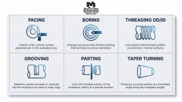
Each operation can be sequenced within the same setup, which reduces handling time and keeps dimensional relationships between features accurate.
What Affects Precision Outcomes in Metal Turning
Precision turning results from the interaction of material behavior, process parameters, machine condition, and operator setup decisions — each one capable of introducing or eliminating dimensional error.
Cutting Parameters
Spindle speed (RPM), feed rate (IPR), and depth of cut interact in complex ways. Too aggressive a cut generates heat and vibration that degrade surface finish and dimensional accuracy. The theoretical surface roughness (Ra) follows the formula Ra = f²/32r, where f is the feed rate and r is the tool corner radius.
A practical sequencing approach from Sandvik Coromant's Technical Guide: maximize depth of cut first to reduce pass count, then optimize feed rate for chip control, and finally adjust cutting speed to balance tool life and surface finish.
Tool Geometry and Condition
The cutting tool's nose radius, rake angle, and insert material (carbide, ceramic, coated inserts) directly affect surface finish and tool life. Flank wear (VB) shortens tool height, directly causing diametral deviation. Per ISO 3685, the maximum flank wear limit for uniform wear is 0.3 mm before replacement.
Beyond this threshold, dimensional drift occurs and surface finish degrades rapidly. Implement in-process probing and automated tool offsets to maintain process capability during long production runs.
Workpiece Material Properties
Material machinability dictates cutting parameters:
| Material Group | Typical Cutting Speed |
|---|---|
| Steel (ISO P) | 140-280 m/min |
| Stainless Steel (ISO M) | 70-130 m/min |
| Aluminum (ISO N) | 300-1000+ m/min |
| Superalloys/Titanium (ISO S) | 25-70 m/min |
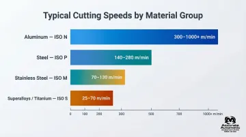
Harder materials require slower speeds, specialized tooling, and aggressive coolant. Softer materials machine more freely but can be prone to built-up edge on the tool.
Machine Rigidity and Condition
Spindle runout, worn bearings, or a poorly maintained lathe introduce variability that no programming or tooling can correct. Machine condition is a foundational factor in sustained precision — one that must be addressed before optimizing any other parameter. Premium CNC lathes incorporate closed-loop linear scales and encoders that automatically compensate for mechanical inaccuracies, leadscrew backlash, and thermal growth.
Thermal Effects and Coolant
Heat generated during cutting causes both the workpiece and machine components to expand. A 1°C shift on a 100mm steel part consumes approximately 1.2 μm of tolerance—enough to breach tight tolerance bands. Coolant application manages temperature to maintain dimensional stability. Parts should be measured at a controlled 20°C temperature to ensure accurate readings and prevent false rejection or acceptance.
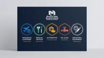
Where Precision Lathe Turning Is Applied
The global precision machining market was valued at $123.54 billion in 2025 and is projected to reach $228.75 billion by 2033, growing at a CAGR of 8.1%. CNC operations account for 78.9% of this market due to their ability to deliver high precision, efficiency, and scalability.
That growth is driven by demand across several industries — each with exacting requirements that only precision turning can reliably meet:
- Aerospace & Defense — Engine rotor shafts, landing gear fittings, and titanium fasteners where tolerances and strength-to-weight ratios are non-negotiable
- Medical Devices — Implantable bone screws, prosthetics, and surgical instruments requiring biocompatible materials and surface finishes of Ra ≤ 0.2 μm
- Automotive — Engine components, transmission shafts, and fuel injection systems built for high-volume repeatability
- Oil & Gas — Valve bodies, connectors, and downhole tools engineered for corrosion resistance and dimensional stability
- Industrial Equipment — Hydraulic cylinders, pump shafts, and precision bearings where consistent geometry determines service life
When to Use Precision Turning
Parts with tight OD/ID tolerances, symmetrical geometries, threaded features, smooth surface finishes, or high-volume repeatability requirements are strong candidates. When dimensional variability from less controlled methods cannot be tolerated, precision turning is the process of choice.
Accurate Automatic MFG brings together experienced machinists, properly maintained CNC lathes, and disciplined quality processes to deliver components that meet specification — every run, not just the first one.
Frequently Asked Questions
What is the difference between precision turning and standard turning?
Precision turning holds tight dimensional tolerances—typically ±0.002" or better—and requires controlled thermal conditions, disciplined machine setup, and in-process inspection. Standard turning focuses on general material removal without strict dimensional requirements.
What materials can be precision turned on a lathe?
Commonly turned metals include steel, stainless steel, aluminum, brass, copper alloys, titanium, and nickel alloys. Machinability varies by material and directly affects cutting parameters and surface finish. Hardened steels up to 60 HRC can be hard-turned with CBN inserts, often skipping secondary grinding.
What tolerances can be achieved with precision metal turning?
CNC precision turning can typically hold tolerances in the range of ±0.002" for general precision work. Achieving extreme tolerances of ±0.0005" is possible on high-end machines but requires meticulous control over tool condition, thermal stability, rigid workholding, and active compensation systems.
How does CNC improve precision in lathe turning compared to manual lathes?
CNC automates tool movement along programmed axes, removing manual feed variation and applying optimized cutting parameters consistently across every part. Manual lathes depend on operator skill for each pass—workable for one-offs, but unable to match CNC repeatability in production runs.
What is the difference between turning and milling?
In turning, the workpiece rotates and the tool is stationary—best for cylindrical, axis-symmetric parts. In milling, the tool rotates and the workpiece is fixed—better suited for prismatic geometries, flat surfaces, and complex 3D profiles.
When is lathe turning not the right process for a part?
Turning is not well-suited for non-cylindrical geometries, flat prismatic parts, or parts requiring machining on multiple non-radial faces. In those cases, milling, grinding, or EDM may be more appropriate. Extremely thin-walled or asymmetric parts may need specialized fixturing or alternative processes to avoid distortion.