Introduction
A single part that's off by 0.1 mm can trigger assembly failures, product recalls, or rejected batches. Toyota's 2024 recall of over 100,000 Tundra and Lexus vehicles due to machining debris left in engine blocks illustrates the downstream cost of precision failures. In aerospace, medical devices, and automotive production, tolerances directly impact safety and regulatory compliance — dimensional accuracy determines whether a part passes qualification or gets scrapped.
Precision turning is a CNC lathe-based machining process that shapes rotating workpieces with stationary cutting tools to produce cylindrical parts with exact dimensions. What follows covers how tolerances work, what affects performance, and what engineers and buyers need to know when sourcing turned parts.
TLDR:
- Precision turning achieves tolerances from ±0.1 mm (standard) to sub-micron (ultra-precision) depending on equipment and material
- Tight tolerances require proper tool selection, thermal management, and workholding — costs scale non-linearly with tighter specs
- Over-tolerancing wastes money — loosening non-critical specs from ±0.01 mm to ±0.03 mm has cut costs by 23%
- GD&T callouts (circularity, cylindricity, runout) prevent spec ambiguity and lock in functional requirements
- Use shops that offer DFM reviews and first-article inspection to catch problems before production runs
What Is Precision Turning?
Precision turning is a CNC lathe-based machining process where a rotating workpiece is shaped by a stationary cutting tool to produce cylindrical parts with exact dimensions.
What separates it from general turning is the requirement for tight tolerances and repeatability at scale: parts must be identical across production runs of hundreds or thousands of units.
The CNC Advantage
Before CNC automation, manual turning relied on skilled machinists to control spindle speed, feed rate, and tool path by hand, typically achieving tolerances around ±0.125 mm with significant operator-dependent variability. CNC precision turning eliminates this variability by automating every aspect of the cutting process. Modern CNC lathes can achieve tolerances as tight as ±0.0025 mm with high repeatability, which is why CNC operations dominate 78.9% of the $123.54 billion global precision machining market.
Core Turning Operations
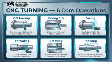
A single CNC lathe setup can complete multiple operations without re-fixturing, reducing handling errors and improving dimensional consistency:
- OD (Outer Diameter) Turning: Removes material from the outside surface to bring a part to its target diameter
- Boring (ID): Enlarges or refines internal diameters — often used where drilled holes need tighter tolerance or better surface finish
- Facing: Machines the end of a workpiece flat and square to its axis, establishing a reference datum
- Threading: Cuts helical threads to precise pitch and depth for fastening or sealing applications
- Grooving: Cuts narrow channels used for O-rings, snap rings, or controlled part separation
- Tapering: Creates conical transitions between diameters, commonly used in shafts and tool shanks
Every re-fixturing step introduces potential errors in concentricity and runout. Completing multiple operations in a single setup eliminates those risk points and tightens overall part consistency.
Understanding Tolerances in Precision Turning
What Is a Machining Tolerance?
A machining tolerance is the acceptable range of variation from a nominal dimension. If a drawing specifies a shaft diameter of 25.00 mm ±0.05 mm, any measurement between 24.95 mm and 25.05 mm is acceptable.
Specifying tolerance correctly matters for both part performance and cost. Tighter tolerances require more time, better tooling, more frequent inspection, and higher scrap rates.
The ISO 286 IT Grade System
The ISO 286-1 standard defines International Tolerance (IT) grades that specify tolerance magnitude for a given nominal size. Lower IT numbers mean tighter tolerances:
| Precision Level | IT Grades | Tolerance Width (25 mm part) | Typical Applications |
|---|---|---|---|
| Ultra-Precision | IT5 | 9 µm (±0.0045 mm) | Diamond turning, precision gears, hard turning |
| High Precision | IT6–IT7 | 13–21 µm (±0.0065–0.0105 mm) | Rolling bearings, precision locating features |
| Standard Precision | IT8–IT10 | 33–84 µm (±0.0165–0.042 mm) | General mechanical assemblies, clearance fits |
A typical "precision turning" tolerance of ±0.025 mm (50 µm total width) falls into IT9, while sub-10 µm requirements demand IT5 capabilities with specialized equipment.
Factors That Make Tight Tolerances Harder to Hold
Several variables work against holding tight tolerances in production:
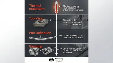
- Thermal expansion: Aluminum 6061 expands 23.6 µm per meter per °C. A 100 mm part with a 10°C temperature rise during cutting expands by 23.6 µm — enough to exceed an IT7 tolerance band entirely. Parts machined while hot will be undersized once cooled to the 20°C inspection baseline.
- Tool wear: As a cutting insert degrades, the effective cutting diameter drifts. In long production runs, this causes gradual dimensional shift that compounds across a batch if tool change intervals aren't controlled.
- Part deflection: L/D ratios above 3:1 make parts flex under cutting forces, producing chatter and inconsistency. Tailstocks and steady rests are not optional for these geometries — they're prerequisites for holding tolerance.
- Fixturing: A 3-jaw chuck introduces more centering error than a collet. Excessive clamping force on thin-walled parts or soft materials causes distortion that shows up as out-of-round or non-cylindrical results.
Understanding what causes dimensional variation makes it easier to specify controls that actually match functional requirements. That's where GD&T comes in.
Geometric Dimensioning and Tolerancing (GD&T)
GD&T (ASME Y14.5) provides unambiguous geometric controls for turned parts:
- Circularity (Roundness): All points on a cross-section must fall between two concentric circles. No datum needed, which makes it straightforward to inspect.
- Cylindricity: Combines roundness, straightness, and taper into a single 3D control — useful when the full bore or shaft surface must stay within a tight envelope.
- Runout: Measures surface wobble relative to a datum axis across a full 360° rotation. Critical for rotating components where imbalance causes wear or vibration.
Engineers should specify these controls on drawings rather than relying on general tolerances alone. A note like "±0.05 mm unless otherwise specified" says nothing about whether concentricity or perpendicularity matters functionally.
GD&T defines the shape and position requirements — but surface finish has its own tolerance implications that interact directly with dimensional accuracy.
Surface Finish and Tolerance Connection
Surface roughness (Ra) measures the arithmetic average of profile height deviations. Finer surface finishes require lighter finishing passes, which also tighten dimensional accuracy:
- Ra 3.2 µm (N8): Standard for general commercial machinery
- Ra 1.6 µm (N7): Typical for standard turning, static mating surfaces
- Ra 0.8 µm (N6): Bearing surfaces, requires precision turning
- Ra 0.4 µm (N5): Fine lapped surfaces, often achieved with hard turning or grinding
Achieving Ra 0.4 µm requires finishing passes that simultaneously narrow the dimensional tolerance band. Specifying both a very tight tolerance and a very fine finish increases machining time and cost significantly — so both should be called out only when the application genuinely demands them.
Key Factors That Affect Precision Turning Performance
Material Machinability
Different materials behave differently during turning. Machinability ratings compare materials to a baseline (AISI 1112 steel or C36000 Brass at 100%):
- Aluminum 6061-T6 (270%): Extremely easy to machine; allows high cutting speeds but requires sharp tools to prevent built-up edge
- Brass C36000 (170%): Free-cutting with excellent chip control and surface finish
- Free-Machining Steel 12L14 (170%): Lead additions reduce friction and heat, prolonging tool life
- Carbon Steel 1018 (70%): Moderate machinability; can be gummy and form built-up edges
- Stainless Steel 304 (40%): High strain-hardening; prone to built-up edge; requires moderate speeds
- Titanium Ti-6Al-4V (20%): Poor thermal conductivity causes extreme temperature rise at the cutting edge
Materials with ratings below 50% require specialized insert coatings, slower speeds, and strict thermal management to maintain dimensional stability.
Cutting Tool Selection and Condition
Insert geometry, coating, nose radius, and tool wear all affect dimensional accuracy and surface finish:
Insert Coatings:
- TiN (Titanium Nitride): Baseline PVD/CVD coating for general wear resistance
- TiCN (Titanium Carbonitride): Harder than TiN; excellent for steel and cast iron
- TiAlN/AlTiN (Titanium Aluminum Nitride): The go-to high-temperature PVD coating for difficult materials (titanium, Inconel, stainless). Forms a protective aluminum-oxide layer that resists oxidation up to 800°C. In one study, advanced TiAlSiN coatings demonstrated 68.8% lower surface roughness compared to traditional TiCN-Al2O3-TiN coatings.
Tool wear gradually shifts part dimensions outside tolerance. Establishing proper tool change intervals based on measured wear patterns is critical for maintaining quality across long production runs.
Cutting Parameters: Speed, Feed, and Depth of Cut
The relationship between cutting speed (SFM/RPM), feed rate, and depth of cut determines both tolerance capability and surface finish:
- Roughing passes: Remove bulk material quickly with higher feed rates and depths of cut; tolerances are looser (IT10–IT12)
- Finishing passes: Optimized for accuracy with high speeds, lighter feed rates, and smaller depths of cut; achieve tighter tolerances (IT7–IT9) and finer surface finishes (Ra 0.8–1.6 µm)
Machinists typically program these as separate operations in the CNC program, with tool changes between roughing and finishing to ensure sharp cutting edges for final dimensions.
Workpiece Setup and Fixturing
How a part is held directly affects runout, concentricity, and chatter:
- 3-jaw chuck: Quick setup but may not center parts as precisely; acceptable for general work
- Collet: Superior concentricity and repeatability for round stock; ideal for precision work
- 4-jaw chuck: Allows manual adjustment for centering irregular shapes
- Between centers: Maximum rigidity for long shafts; supports both ends
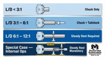
Length-to-Diameter (L/D) Ratio Guidelines:
- L/D < 3:1: Chuck only is acceptable
- L/D 3:1 to 6:1: Tailstock support required
- L/D 6:1 to 12:1: Steady rest support mandatory
- Special case: If internal operations (boring, drilling) are required on the end face where a tailstock cannot be used, a steady rest is mandatory if L/D exceeds 2.5:1
Improper clamping force can distort thin-walled parts or soft materials, causing dimensional errors that persist even after the part is released.
Machine Condition and Calibration
Spindle bearings, linear guides, and thermal compensation systems all set the ceiling on what a CNC lathe can actually hold. Temperature fluctuations in the cutting zone, workpiece, or machine structure cause thermal drift, which is one of the most consistent sources of dimensional variation in production turning.
Machine Builder Compensation Strategies:
- Okuma Thermo-Friendly Concept (TAS): Uses temperature sensors on the spindle and casting to provide real-time feedback to the CNC control, automatically compensating for thermal deformation
- Mazak Ai Thermal Shield: Utilizes spindle speed and temperature sensor data, combined with machine learning from post-machining measurements, to optimize thermal displacement offsets
Regular calibration and a temperature-controlled shop environment are non-negotiable when holding tight tolerances across high-volume runs.
Best Practices for Precision Turning Success
Design for Manufacturability (DFM)
Engineers should design parts that are cost-effective to manufacture:
- Specify only the tolerances the part's function requires: one case study showed relaxing non-critical tolerances from ±0.01 mm to ±0.03 mm cut machining costs by 23%
- Use standard tooling geometry: Features accessible with standard inserts and boring bars reduce setup time and cost
- Keep wall thickness consistent: Thin sections deflect and distort under cutting forces
- Avoid sharp internal corners: Turning produces radiused corners; sharp internal corners require secondary operations
These decisions lock in cost and lead time early — before a single chip is cut.
Communicate Clearly with Your Machine Shop
Provide complete, unambiguous drawings with:
- GD&T callouts: Specify circularity, cylindricity, runout, and other geometric controls where functionally required
- Material specifications: Include grade, condition (e.g., 6061-T6, 304 annealed), and any heat treatment requirements
- Surface finish requirements: Specify Ra values for critical surfaces
- Special inspection or certification requirements: Material certs, first-article inspection reports, dimensional reports
Vague or incomplete prints are a leading cause of non-conforming parts and costly reruns. If a drawing leaves a dimension open to interpretation, your machine shop will make an assumption — and it may not match your intent.
Build in a Quality Inspection Plan
First-Article Inspection (FAI) is a critical step where the first produced part is measured against every drawing dimension before the full run proceeds. This validates that the manufacturing process can meet all specifications.
Common Inspection Tools for Turned Parts:
- Coordinate Measuring Machines (CMMs): High-accuracy dimensional verification with sub-micron to 5 µm uncertainties
- Air gauges: Ideal for internal diameters with very tight tolerances (IT2–IT7); repeatability <0.5 µm without scratching the part
- Bore gauges: Electronic bore gauges provide repeatability <0.5 µm for internal diameter verification
- Optical comparators: Non-contact profile measurement with accuracies down to ±0.7 µm
In-process gauging during long runs ensures dimensional consistency as tool wear progresses. Statistical Process Control (SPC) can identify trends before parts drift out of tolerance.
Partner with an Experienced Precision Manufacturer
Working with a precision machine shop that has deep turning expertise means tolerance feasibility reviews, material selection guidance, and proactive communication are built into the process — not addressed after a non-conformance report lands on your desk.
Accurate Automatic MFG provides CNC turning, CNC milling, and screw machine work for industrial clients who need tight tolerances and consistent quality across production runs. Their team prioritizes workmanship and builds long-term customer relationships grounded in integrity. For precision turning projects, reach them at sales@accurateautomaticmfg.com or call +1 330-435-4575.
Common Applications of Precision Turned Parts
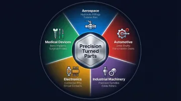
Precision turned parts are essential across industries that demand tight tolerances, high reliability, and regulatory compliance:
- Automotive — Shafts, valve bodies, bushings, transmission components, and bearing seats. The automotive sector drives significant demand: the global precision machining market was valued at $123.54 billion in 2025 and is projected to reach $228.75 billion by 2033.
- Aerospace — Fittings, fasteners, fuel system components, landing gear parts, and structural connectors. These applications typically require material certifications and first-article inspection per AS9102 standards.
- Medical Devices — Implants, surgical instrument components, connectors, and delivery system parts. Biocompatible materials and strict dimensional control are required to meet FDA regulations.
- Electronics — Pins, housings, heat sinks, connectors, and precision fasteners, often produced in high volumes with tight consistency requirements.
- Industrial Machinery — Spindles, rollers, gears, hydraulic components, and tooling, frequently in hardened materials that require finish hard turning.
What Makes a Part Ideal for Precision CNC Turning?
Not every part is a natural fit for turning. These characteristics signal a strong candidate:
- Cylindrical or rotationally symmetric geometry that can be machined around a central axis
- Tight OD/ID concentricity requirements — turning machines all features relative to the same rotation axis, making concentricity a natural outcome
- High-volume runs where CNC automation delivers repeatable accuracy across thousands of identical units
- Complex thread profiles or precise tapers, which CNC lathes can produce in a single setup
Finish Hard Turning as an Alternative to Grinding
Finish hard turning uses Polycrystalline Cubic Boron Nitride (PCBN) or ceramic inserts to machine hardened steel components (45–67 HRC range) that historically required cylindrical grinding. Hard turning can achieve IT5–IT6 tolerances and surface finishes of Ra 0.2–0.8 µm, making it a practical grinding replacement for automotive bearing seats, tooling components, and similar applications where IT5–IT6 is acceptable.
Hard turning offers three practical advantages over grinding:
- Single-setup machining reduces cycle times compared to multi-setup grinding
- Dry cutting eliminates coolant waste and disposal costs
- 80–90% of cutting heat transfers into the chip rather than the workpiece, preserving the material's microstructure
Grinding remains necessary for mirror finishes (Ra < 0.1 µm) or IT4 tolerances, but hard turning replaces grinding for many applications where IT5–IT6 is sufficient.
Frequently Asked Questions
What is the definition of a precision turn?
Precision turning is a CNC lathe process that removes material from a rotating workpiece using a stationary cutting tool to achieve exact dimensions and tight tolerances. Unlike general turning, it prioritizes accuracy, repeatability, and holding tolerances in the IT5–IT9 range across production runs.
What is the difference between CNC and HMC?
CNC (Computer Numerical Control) is the control technology used across many machine types including lathes, mills, and routers. HMC (Horizontal Machining Center) is a specific type of milling machine with a horizontal spindle orientation, typically used for multi-sided machining of prismatic parts.
What tolerances can precision CNC turning achieve?
Standard CNC turning achieves ±0.05–0.1 mm (IT9–IT10), precision turning can hold ±0.01–0.025 mm (IT7–IT8), and ultra-precision operations with specialized equipment and diamond tooling can reach sub-micron tolerances (IT5 or tighter). The achievable range depends on material, part geometry, machine capability, and thermal management.
What materials can be precision turned?
Common machinable metals include aluminum (6061, 7075), brass (C36000), steel (1018, 4140), stainless steel (303, 304, 316), and titanium (Ti-6Al-4V). Engineering plastics such as PEEK, Delrin (acetal), and PTFE can also be precision turned. Material selection drives cutting parameters, tooling choices, surface finish outcomes, and overall cost.
How does surface finish relate to tolerance in precision turning?
Finer surface finishes require lighter passes at reduced feed rates, which also tighten dimensional accuracy. Specifying both a tight tolerance (e.g., ±0.01 mm) and a fine finish (e.g., Ra 0.4 µm) increases time and cost, as it demands multiple finishing passes and more frequent tool changes.
What industries use precision turned parts most?
Aerospace, automotive, medical devices, and electronics are the highest-demand sectors — each requiring tight tolerances, high reliability, and compliance with strict regulatory standards. Automotive and aerospace are the primary drivers behind the precision machining market's projected 8.1% CAGR through 2033.