Introduction
Manufacturers face relentless pressure to cut cycle times and hold tight tolerances across high-volume production runs. Single-spindle turning forces operators to manually unload, flip, re-chuck, and re-indicate parts before machining the second side—introducing idle time, positioning errors, and throughput bottlenecks that compound quickly at volume.
Twin spindle CNC turning eliminates that bottleneck. Two opposing spindles transfer parts mid-cycle automatically, enabling first- and second-operation machining in a single uninterrupted sequence.
This guide covers how the technology works, where it delivers the strongest efficiency gains, and how to evaluate whether twin spindle turning fits your production requirements.
Key Takeaways
- Twin spindle CNC turning machines transfer parts between opposing spindles automatically, finishing both ends in a single cycle
- Running both operations simultaneously cuts per-part cycle time by 30–50% versus sequential single-spindle setups
- Ideal for high-volume, cylindrical parts requiring machining on both ends—common in automotive, aerospace, and industrial applications
- Best fit depends on part geometry, production volume, concentricity requirements, and cost-per-part ROI
What Is CNC Turning and Why Twin Spindle Technology Matters
Defining CNC Turning
CNC turning is a subtractive manufacturing process where a rotating workpiece is shaped by a stationary cutting tool under precise computer control. The process encompasses a range of operations:
- Outer diameter (OD) and inner diameter (ID) turning to create cylindrical surfaces
- Facing to machine flat end surfaces
- Boring to enlarge existing holes
- Threading to cut internal or external threads
- Grooving to create recesses or channels
- Parting/cutoff to separate finished parts from bar stock
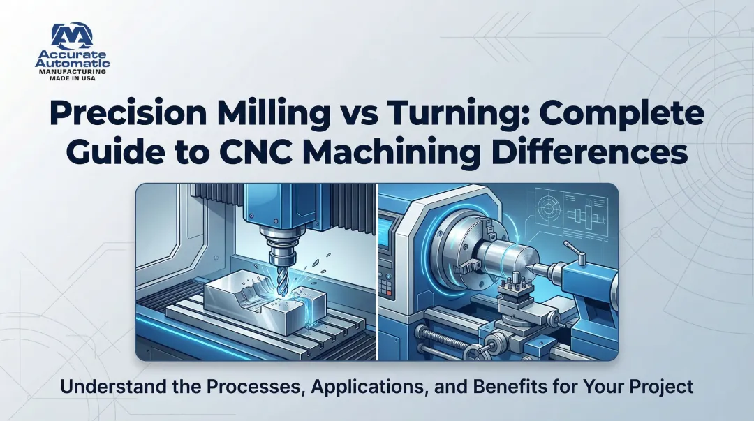
Unlike CNC milling—where the tool rotates and the workpiece remains stationary—turning relies on workpiece rotation. This fundamental difference makes turning ideal for cylindrical and rotational components.
The Single-Spindle Bottleneck
Traditional single-spindle turning creates a significant operational bottleneck when parts require machining on both ends. After completing the first operation, the operator must:
- Manually unload the part from the spindle
- Flip and re-orient the workpiece
- Re-chuck the part in the same machine or transfer to a second lathe
- Re-indicate to establish a new datum reference
- Begin the second-operation machining
This manual intervention introduces non-value-added time, accumulates work-in-process (WIP) inventory between operations, and creates opportunities for handling damage. Worse, every manual re-fixturing introduces positioning errors that compromise concentricity and runout between front and back features.
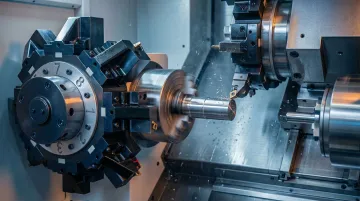
Twin Spindle Technology: The Evolution
Twin spindle turning centers eliminate the re-chucking bottleneck through an automated part transfer sequence. These machines feature a main spindle and a directly opposing sub-spindle arranged face-to-face along a common axis. Once the main spindle completes first-operation machining, the sub-spindle automatically advances, grips the finished end of the part, and accepts the transfer within the machine cycle—no operator input required.
While the sub-spindle machines the second end of the transferred part, the main spindle is already gripping the next piece of bar stock. Both operations run at the same time, cutting total cycle time roughly in half compared to sequential two-setup turning.
Key advantages over single-spindle setups include:
- Eliminates manual re-chucking and repositioning between operations
- Reduces WIP inventory by completing both ends in one machine cycle
- Maintains concentricity without re-indicating on a second datum
- Increases throughput without adding operators or floor space
How Twin Spindle CNC Turning Works: The Operational Flow Explained
Main Spindle First-Operation Sequence
The main spindle grips raw bar stock (fed continuously via a bar feeder) or a pre-cut workpiece loaded into the chuck. It then performs first-operation turning to programmed specifications:
- OD turning to establish outer diameters
- Facing to create the front datum surface
- Boring internal features
- Threading external or internal threads
- Grooving and other detail work
Once first-operation machining is complete, the part remains in the main spindle chuck, ready for automated transfer.
Automated Part Transfer: The Critical Handoff
The part transfer sequence is the defining feature of twin spindle technology. The process unfolds as follows:
Spindle Synchronization: The machine engages Synchronous Spindle Control (SSC), matching the exact RPM and angular phase (C-axis position) of both the main and sub-spindle. This ensures the sub-spindle approaches at precisely the correct rotational position.
Sub-Spindle Advance: The sub-spindle travels along its Z-axis (or B-axis, depending on machine configuration) toward the main spindle. Advanced machines use torque skip functions to monitor axis load, allowing the sub-spindle to seat firmly against the workpiece without crushing it.
Grip and Release: The sub-spindle chuck or collet clamps onto the finished end of the part (triggered by specific M-codes such as M110/M111). Once the sub-spindle has a secure grip, the main spindle releases its hold.
Retraction and Cutoff: The sub-spindle retracts, pulling the part clear of the main spindle work zone. If the part was bar-fed, a cutoff tool separates the workpiece from the remaining bar stock. Stress control macros verify successful part separation before the sub-spindle continues.
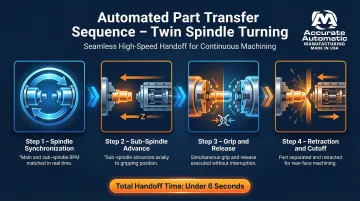
This entire handoff sequence occurs in under 6 seconds on high-speed machines, enabling total cycle times as short as 16 seconds for small, simple parts.
Parallel Operations: The Efficiency Core
Once the sub-spindle has accepted the part, both spindles operate simultaneously:
- Sub-spindle: Machines the second end of the transferred part (second-operation turning, boring, threading, facing)
- Main spindle: Grips the next piece of raw material and begins first-operation machining on a new workpiece
The effective cycle time per completed part equals the duration of the longer operation—not the sum of both. That distinction is what makes twin spindle turning so productive in high-volume runs.
Live Tooling and Multi-Feature Machining
Modern twin spindle turning centers often incorporate live tooling via Built-in Motor Turrets (BMT). These powered tool stations allow the machine to perform milling, drilling, and tapping operations within the same cycle, functioning as a turn-mill center.
Key capabilities include:
- C-axis indexing to 0.0001° for precise angular features
- Y-axis travel for cross-holes, flats, and asymmetric off-center features
- Multi-station turrets with up to 12+ tool positions for complex sequences
By using live tooling on both spindles, manufacturers complete parts with milled flats, cross-drilled holes, and tapped features in a single automated cycle—eliminating secondary milling operations entirely.
Automation Integration for Lights-Out Production
Twin spindle turning centers achieve their full potential when integrated with peripheral automation:
- Bar feeders supply raw bar stock through the main spindle continuously, enabling unattended runs lasting hours or full shifts
- Gantry loaders handle pre-cut workpieces (castings, forgings) for high-speed automated loading
- Parts catchers eject finished components from the sub-spindle at the end of each cycle
- Stockers and accumulators collect and organize finished parts, preventing damage between cycles
With a bar feeder and parts catcher running together, the twin spindle lathe becomes a fully closed-loop manufacturing cell. Operator intervention drops to roughly 15 minutes per hour.
Efficiency Gains: How Twin Spindle Turning Cuts Cycle Time and Cost
Cycle Time Reduction: The Simultaneous Operations Advantage
Consolidating first-operation and second-operation into a single twin spindle machine cuts cycle time significantly. Industry data shows automated part transfer sequences can boost annual throughput by up to 40% for high-volume parts by eliminating manual re-chucking and enabling parallel processing.
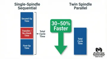
How it works:
- Single-spindle sequential: Total cycle time = First-op + Transfer + Second-op time
- Twin spindle parallel: Total cycle time ≈ Duration of the longer single operation
Because both operations run simultaneously on consecutive workpieces, the per-part cycle time drops to approximately the duration of the longer single operation — not the combined total of both.
Precision Through Automated Transfer
Manual re-fixturing introduces stack-up positioning errors that compromise concentricity and perpendicularity between front and back features. Direct spindle-to-spindle transfer eliminates this error source, achieving coaxiality tolerances as tight as ±0.006mm.
Quality benefits include:
- Preserves the original work-holding datum for consistent part-to-part accuracy
- Eliminates operator-induced runout variation by removing manual re-indicating
- Supports strict front-to-back concentricity requirements (common in aerospace and medical applications) at any production volume
The result: fewer inspection escapes, lower scrap rates, and measurably better process capability — without adding inspection steps.
Labor and Floor Space Consolidation
Replacing two sequential single-spindle lathes with one twin spindle machine delivers real facility benefits:
Floor space:
- Twin spindle turning centers reduce floor space by 30% compared to two separate 2-axis lathes
- Eliminates WIP staging areas between OP1 and OP2 machines
- Frees shop floor space for additional capacity or improved workflow layout
Labor:
- Consolidates two-machine, two-operator setups into a single machine
- Automated cells require operator attention for roughly 15 minutes per hour
- One operator can tend 3-4 twin spindle machines simultaneously
- Frees skilled operators for setup, programming, and quality control work
Tooling and Setup Simplification
Twin spindle machining consolidates tooling requirements across the board. One set of workholding, one tool package, and one program replaces the dual-setup model. Switching between part families means coordinating a single machine instead of two, which cuts changeover time and simplifies tool crib inventory management.
Quality Consistency: Completed Parts, Reduced Handling
Parts machined in a single continuous cycle exhibit superior quality consistency. Running both operations on one machine eliminates inter-machine transfers — removing the risk of handling damage, mixed batches, or contamination.
A single machine environment also ensures consistent cutting conditions, coolant flow, and thermal stability throughout the cycle. With fewer handoffs, there are fewer points where inspection escapes can occur.
Industries and Parts Best Suited for Twin Spindle Turning
Ideal Part Geometries
Twin spindle turning delivers maximum value for specific part geometries:
Best-suited parts:
- Short-to-medium length cylindrical components requiring machining on both ends
- Shafts with features on both faces (threads, grooves, bores)
- Flanged bushings and sleeves
- Connector bodies and housings
- Valve components (bodies, stems, plugs)
- Hydraulic and pneumatic fittings
- Gearbox components and transmission parts
Length-to-Diameter (L:D) ratio considerations:
- Parts with L:D ratios up to 3.5:1 or 4:1 are ideal for standard twin spindle chucking without additional support
- Parts exceeding 4:1 L:D may require steady rests or follow rests to prevent deflection and vibration
- Very long, slender parts (7:1 L:D and beyond) are better suited for Swiss-type sliding headstock lathes with guide bushing support
Industries Relying on Twin Spindle CNC Turning
Several industries depend on twin spindle turning for parts that demand both-end machining in a single setup:
- Automotive Powertrain: Camshafts, gearbox components, clutch housings, and transmission parts—often with tight concentricity requirements between bores and external diameters
- Aerospace Fasteners & Fittings: Fluid fittings, structural fasteners, and connector bodies requiring AS9100 traceability and zero handling damage; single-setup processing eliminates mixed-batch risk
- Medical Device Manufacturing: Orthopedic implants, surgical instrument components, and vascular device housings where single-cycle machining eliminates secondary heat-treating or welding steps
- Oil & Gas / Industrial Fluid Control: Valve bodies, valve stems, and hydraulic fittings needing threading and boring on both ends, with automated transfer ensuring precise alignment between fluid channels
Not every part geometry fits this model, though. Understanding the limitations is just as useful as knowing the strengths.
Parts Less Suited for Twin Spindle Technology
Not ideal:
- Very long shafts exceeding the machine's sub-spindle reach (typically over 4:1 L:D without steady rest support)
- Highly asymmetric or prismatic parts better suited for multi-axis milling centers
- Extremely low-volume one-off parts where complex setup costs outweigh cycle time savings
- Parts requiring only one-end machining (no second-operation features to justify sub-spindle transfer)
Choosing Twin Spindle CNC Turning: Decision Framework for Manufacturers
Production Volume Threshold Considerations
Twin spindle setups involve more complex programming, tooling investment, and initial setup time compared to single-spindle operations. Manufacturers must evaluate whether their annual part volumes justify the setup amortization.
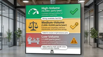
Qualitative framework:
High-volume production (10,000+ parts/year): Strong candidate for twin spindle investment. Per-part efficiency gains compound rapidly across large production runs, delivering fast ROI through reduced labor and cycle time.
Medium-volume production (1,000–10,000 parts/year): Viable if parts have complex both-end features or tight concentricity requirements. Eliminating re-fixturing error can justify twin spindle use even at moderate volumes by reducing scrap and rework costs.
Low-volume production (<1,000 parts/year): Better suited for single-spindle or manual operations unless parts have extreme precision requirements that make manual re-chucking prohibitively risky.
These thresholds shift considerably based on part complexity, cycle time, and labor rates. A complex aerospace fitting with a 45-minute cycle may justify twin spindle processing at far lower volumes than a simple bushing with a 90-second cycle.
Part geometry is the other half of the equation — and often the more decisive one.
Part Complexity as a Deciding Factor
Part geometry and feature requirements often matter more than volume:
Strong twin spindle candidates:
- Parts requiring machining on both ends (front and back features)
- Components with tight concentricity requirements between opposing features (±0.010mm or tighter)
- Parts with complex secondary operations (cross-holes, flats, tapping) completable with live tooling in-cycle
- Components where manual re-fixturing introduces unacceptable positioning error
Weaker candidates:
- Parts requiring only one-end machining with no second-operation features
- Simple geometries with loose tolerances where re-chucking introduces minimal error
- Parts better suited for screw machine operations (very small, high-speed production)
Once you've assessed part complexity, the next question is whether to run twin spindle operations in-house or partner with a shop that already has the equipment.
Make-vs-Outsource Decision
Many manufacturers find it more cost-effective to partner with a precision CNC turning shop that already operates twin spindle equipment rather than capitalizing their own machines.
Considerations favoring outsourcing:
- Twin spindle turning centers carry significant upfront cost — typically $150,000–$500,000+ depending on configuration and automation level
- Multi-spindle synchronization and live tooling programming requires specialized CAM knowledge most shops don't have on staff
- Utilization: If your volumes don't support 60%+ machine utilization, outsourcing typically delivers better per-part economics
- Contract shops like Accurate Automatic MFG already carry the equipment investment and process expertise — you pay per finished part rather than per machine hour sitting idle
Considerations favoring in-house investment:
- Sustained production runs that keep machines busy across multiple shifts justify the capital outlay
- Core competency: When turning is central to your product line and competitive differentiation, ownership makes strategic sense
- Critical parts requiring ITAR compliance, IP protection, or tightly controlled lead times often demand in-house manufacturing
- Existing infrastructure: Available floor space, skilled operators, and established tooling supply chains lower the effective entry cost
Key Decision Criteria Summary
Evaluate these factors when choosing twin spindle turning:
| Decision Factor | Twin Spindle Advantage | Single-Spindle May Be Better |
|---|---|---|
| Production Volume | High-volume recurring runs (5,000+ parts/year) | Low-volume, sporadic orders (<500 parts/year) |
| Part Geometry | Both-end features required | One-end machining only |
| Concentricity Tolerance | Tight front-to-back concentricity (±0.010mm or better) | Loose tolerances, no critical alignment |
| Floor Space | Limited space, need to consolidate operations | Ample floor space available |
| Labor Availability | Skilled operator shortage, need automation | Abundant manual labor, low labor costs |
| Total Cost-Per-Part | Lower when cycle time reduction and quality gains are factored | Lower for simple, low-volume parts |
Frequently Asked Questions
What is turning in a CNC machine?
CNC turning is a subtractive manufacturing process where a cylindrical workpiece rotates against a stationary cutting tool controlled by a computer program. The process produces cylindrical features such as diameters, bores, threads, and grooves with high repeatability and precision.
What is a twin spindle CNC turning machine?
A twin spindle turning machine features a main spindle and a directly opposing sub-spindle arranged face-to-face. This configuration allows the machine to automatically transfer a part mid-cycle and machine both ends in a single, uninterrupted operation without operator intervention.
How does a sub-spindle differ from a main spindle in CNC turning?
The main spindle holds and rotates the raw workpiece for first-operation machining. The sub-spindle accepts the partially completed part via automated transfer, grips it securely, and performs second-operation machining on the opposite end while the main spindle begins the next workpiece.
What types of parts are best suited for twin spindle CNC turning?
Short-to-medium cylindrical components requiring machining on both ends benefit most—such as bushings, valve bodies, connector housings, and shaft ends. High-volume production runs gain the most, since faster cycle times translate directly into lower per-part costs.
How does twin spindle turning reduce cycle time compared to single spindle?
First-operation and second-operation run simultaneously on consecutive workpieces. This means per-part cycle time equals roughly the duration of the longer single operation—not the combined total. The parallel processing approach can cut cycle times by 30-50% compared to sequential single-spindle setups.
Is twin spindle CNC turning cost-effective for smaller production runs?
The efficiency advantage grows with volume, but even medium-run parts with tight concentricity requirements can justify twin spindle use. Eliminating re-fixturing error reduces scrap and rework costs regardless of batch size, making it a sound choice for precision components at moderate volumes too.